by Lokesh Aravapalli · Jane Street ASIC Puzzle 2026
Reverse engineering an ASIC.
per arenam ad astra — "through the sand, to the stars"
From GDS polygons and waveforms to SMT solving, Morse code, a leap
second, and an 11×11 Star Battle puzzle hidden inside the silicon.
00 / story
Starting with.
I started with a physical layout and a question: what does this circuit actually do?
Very short summary of the page
Jane Street published a chip and asked people to reverse-engineer it from its raw physical layout(GDS file);without names and netlist; I did.
I recovered a netlist from the raw file and then built a simulator, and used a solver to find the exact 121-bit input that makes it succeed.
The string that I extracted is (* TWO STARS *).
I also rebuilt parts of the circuit I extracted from the GDS file to help me understand them better, such as
11-cycle resets and >=2 counters.
You can see them here:
CircuitVerse
.
Upon exploring it a lot, looking and tracing through the gates, I found the given chip is checking whether a 121-bit input is a valid solution to an 11×11 Star Battle puzzle (a real puzzle), not a random correct sequence. There's a playable version of the exact puzzle later on this page.
Found a few Easter eggs including: Letters JSC in the extracted regions which could mean Jane Street Capital, Morse code that spells PER ARENAM AD ASTRA, a leap second and the string EGG' itself in the file contents which is likely coincidental.
what each section means, 1.story: how i found this puzzle and netlist extracttion, and simulating a few inputs; 2. solver: how I used Z3 solver to few parts;
3. star battle: exploring the circuit like how it works and whats in there; finally finding the region layout of STAR BATTLE puzzle that chip is checking if the input satisfies;
4. easter eggs: how I found them.
121input bits
36dummy cells
11×11star battle grid
2methods
Approach, briefly
I recovered the netlist directly from the GDS's raw file by polygon merging with union find; no
cell names exist other than what a standard-cell library provides. Used python to build a gate-level simulator. Validated the pipeline on
a known warm-up circuit before using it on the real chip, faced bugs that ate a lot of time.
After building the gate level simulator; I tried forcing success to high directly (didn't work;
the output depends on the real input data, not just the flag), then decoded the 8-bit output stream as
ASCII and found the chip output changes based on the answer (TRY AGAIN, EMPTY SKY,
BIG BANG, TWO"NOT TOUCH). Guessing doesn't seem to find a 121-bit answer by hand, so switched to Z3 solver,
unrolling the chip's clocked behavior symbolically and asking it directly to find a input that makes the success high;
then I used the sequence given to me by the solver which is how (* TWO STARS *) got found for the first time.
Still not knowing what that 121-bit input actually mean, I went back and analyzed the
whole circuit carefully; the internal counters, how bits get routed and latched, all the way
to the success itself; rebuilt a few of the more interesting pieces as real working circuits
, just to watch them run; You can see them here:
CircuitVerse
; before finally hunting for the Easter
eggs they mentioned, I found few of these easeter eggs before solving the circuit and few after solving the circuit. Found three which I think are real
and one which I think is not: The letters JSC the short form of "Jane Street Capital"
visible from the shapes of 3 extracted regions of the puzzle,
Morse code buried in negative-Y coordinate far from the actual die area
placement, that spells PER ARENAM AD ASTRA, and a leap second timestamp in the VCD
file. A strong fourth; the word "EGG" in a png file's raw bytes;
turned out almost certainly coincidental; no characters around the area make sense to me other than seeing the EGG there.
That answer (* TWO STARS *) made sense once found the chip is checking an 11×11 Star
Battle puzzle's solution, found from the clues hidden in the ROM.
Extracting the region map; the one part of the puzzle that was never asked directly;
was recovered in two ways: once by sending selected pairs of inputs (fixed a reference and moving the pair)
through the chip and watching which flops react, filtered down using a few geometrical constraints,
and other by symbolically tracing which grid cells each internal flop depends on; and
both methods agreed on the regions;
cell for cell.
Now this is going to be a loooooong read;
Grab a Coffee!
How I ended up here
A bit of context first, because that is why I actually wanted to complete it this time.
A few months before this, Jane Street ran the
Advent of FPGA
challenge, which is a set of problems to actually implement on an FPGA. I found it late, didn't have enough
time to solve everything, and missed the submission deadline.
I really did want to solve it though. :cry:
One thing I did that time which is good: I subscribed to Jane Street's blog right after missing that
deadline, so I will know about the next one in time if there is any. Which is exactly why I ended up seeing this
puzzle the same day they released, and got the email.
The puzzle
You know about this already, probably; but just in case you don't: Jane Street published a puzzle called
"Can You Reverse Engineer an
ASIC?". They designed a small chip, ran it through a physical-design flow, and gave only
what you actually need to manufacture it -- a puzzle.gds file (the raw physical layout),
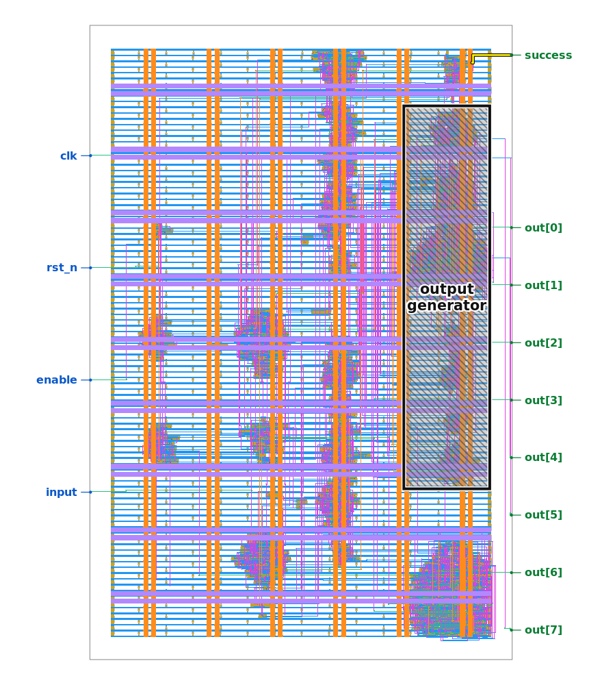
a image of the layout with few lables, and a VCD waveform file of somebody entering a
wrong answer. Also, they mentioned that there
are a few Easter eggs hidden, including in the places that you don't need to look at to solve the actual
puzzle.
the layout image provided in the repo
Along with the real puzzle, they also gave a small warm-up: an 8-bit adder whose output is true when
A + B == 496, gave every stage intermediate files of the flow; the original Verilog source, the
synthesized netlist, the placed-and-routed layout, and the final GDS. The idea is: build some tool and test it
on the warm-up puzzle first, for which you already know the right answer, before trying it on the real puzzle.
fun fact, since I like this kind of detail: 496 is the third perfect number; 6, 28, 496, ... and so on; a number equal to the sum of its own proper divisors.
The real chip have six pins: clk, rst_n, enable as controls,
a single-bit I which is a serial input, an 8-bit O[7:0] output bus, and a success
flag. Send something and make the success go high, this is the target.
Extracting the netlist from gds file
A GDS file is just geometry; lots of rectangles on a few numbered layers, arranged in a hierarchy of cell
placements. So the first real task is recreating an actual
netlist from it (which pin connects to which pin) entirely from the raw file.
One thing that made this solvable in first place is: the GDS had the standard-cell library names as instance
references (sky130_fd_sc_hd__a21bo_2, sky130_fd_sc_hd__and2_2, and so on).
If they had give us only the layout, recognizing a gate from raw transistor layout is the part which would have taken me a year to figure out :just kidding but its true,
and they gave us this; every instance is a known, pre-characterized SkyWater cell, and each one's
library definition carries text labels naming its pins. So the whole now the problem is just one
question: which pins are wired together?
1. Flatten the GDS's hierarchy into relative coordinate with a reference point.
2. Convert every path into a polygon; GDS stores shapes like this too.
3. Merge touching/overlapping polygons on the SAME metal layer into one net.
4. For every via there on in the gds, merge the shapes below and above it.
5. This results in a netlist.
6. Then, we can simulate the netlist, and see what it does, by pulling the actual definations from the library we know what each cell does.

Same-layer overlap = connected. Different layers = if via connect them, it means they are connected.
Built with gdstk to read/flatten the GDS and shapely and then
actually merge the geometry into nets. For gate semantics, I referred to the real
functional model for every cell type straight from SkyWater's open-source library,
because this is the only way to be sure of what a cell does.
Bug Bug Bug . . .
This is the part the single biggest chunk of time lost on this
whole puzzle without a progress. It happened before I even touch the real puzzle.
I was taking AI's help writing the actual extraction code; describing what I
wanted, getting Python back, running it. Ran it against the warm-up, and something was clearly wrong;
not everything, but enough that I can tell it wasn't right.
obviously something is wrong here, but what? I don't actually understand the
extraction implementation enough to spot it just by reading the code
Sat with the code later that day, slowly working through it line by line, before it clicked:
rotation units. The raw GDS file format itself stores rotation in degrees;
that's just how GDSII defines it. But gdstk, the library actually reading the
file, converts that value to radians internally before ever handing it to me.
So by the time my own code read cell's rotation, it was already in radians;
but I didn't know that first, and ran it through one more degrees-to-radians conversion on that.
Every rotated pin's computed position
must be wrong, which doesn't crash anything; but it silently put the
cells in the wrong places depending on whether the rotation is involved. I had spent time
trusting the code that looked completely reasonable, because it was reasonable; it just made one
very simple, but very wrong assumption about the units which the library is giving us the numbers in.
Validating this on the warm-up and going to real puzzzle
Once that was fixed, the warm-up adder simulated correctly end to end. Fed it two 8-bit values,
watched the success go high when they sum up to 496. This woked; now I can move to the real puzzle.
So, I moved to the actual puzzle. Extracted the same way: gates and connectivity.
And then the obvious question in mind: okay, I have a netlist. What does it do? What's
the input, what's the output, what is this circuit for?
The puzzle's page had one useful line there:
"There is one section of the design that is used to generate the output but does not affect
the success output. You can safely ignore it for the initial reverse-engineering steps."
Which felt like the goal is making success go high, and the string comes
as the output from the circuit, simple!.
which is basically right, but doesn't end there;
Seeing the waveform file, and a hint
Before touching the real input search, I looked at the example trace they gave;
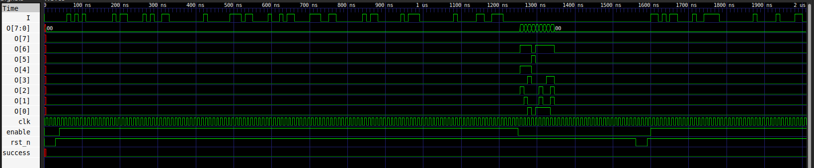
example_inputs.vcd, a dump file of somebody entering wrong input. Its version string said,
verbatim: "Leave no stone unturned! But for this file, consider looking at it in a waveform viewer
instead." So I did.
Obviously success never goes high in it; They won't reveal the correct answer in example traces.
But watching
two back-to-back attempts in the trace made something click: the circuit takes 120+ clock
cycles after the first input bit before it produces its output. That's a big number
already in my mind 2 power 120 possible inputs?, and cycle count is something that tells us something about the sequence length;
I didn't know how yet.
you can see there is some output after a lot of cycles after the reset
Forcing the success to high
First idea: what if I just forcesuccess high directly, without looking for what
the actual input needed, and read whatever comes out the output pins?
Didn't work; the output generator clearly also depends on the actual input data, not just
on the success flag as a trigger. Forcing the flag with the wrong data, and you just get the same
kind of stream you get from any other wrong attempt.
Okay, then: what does this 8-bit output stream even mean? It comes out in
parallel, 8 bits at a time.
what numbers are these
Writing down the raw values made no sense at first; looked like random bits. Then, they mentioned about the string
in write-up yeah: they are ASCII. And once I did:
TRY AGAIN
lol, I thought this was some kind of clue hidden in the VCD traces at first,
not just... the chip telling me I am wrong
The guessing phase
Once I it outputs the messages in ASCII, the obvious next move was trying the obvious inputs.
All zeros → EMPTY SKY
All ones → BIG BANG
Alternating patterns (0101..., 1010...) → TRY AGAIN
Random bit flips in an otherwise-zero sequence → TRY AGAIN
Then something really confusing: I tried all-zeros, then all-zeroes except a single 1 at a random
positions. EMPTY SKY... then TRY AGAIN... and then, right at the very
last bit position when made it high, EMPTY SKY again.
how? why? I assumed EMPTY SKY specifically meant "literally all zeros";
but whatever the first ~121 bits already satisfy, the last bit doesn't change the verdict.
Maybe the current input sequence already satisfies whatever is being checked for without depending on the last bit
or there might be multiple solutions for this puzzle
I still don't know the actual input sequence length required, other that what i inferred from the cycle count in VCD file
Same when flipping just the last bit of an all-ones sequence; still BIG BANG, no
matter what that final bit was.
That's when I started thinking about a number: 122 total cycles, but if the very last one genuinely
doesn't matter... maybe the circuit only actually cares about 121 of them. And 121 is a
perfect square; 11×11.
arranging 122 things nicely is awkward; 2×61 is not a shape anyone want to design around(atleast me).
121 as an 11×11, though, that's suspicious; in a good way
did I put it together right then? nope. not even close. must be dumb :I (kidding)
I kept trying structured guesses anyway; walking a single 1 bit one position at a time,
various prefixes; TRY AGAIN, every time.
Yeah; I will try again.
But forcing and guessing clearly wasn't giving me what I want; the search space is very large, and
nothing when used the random bits was converging.
01 / solver
I asked a solver.
2¹²² possibilities is hard to brute force.
At this point the only real way i think exist was using some equation solver; specifically Z3 which I used.
Instead of trying guesses, we can unroll the chip's behavior
symbolically over a number of cycles, treat every input bit as a variable, and then ask the solver
directly; does any combination of values to these variables make success go high? If it returns
true, it gives us back the exact bits. If it says no, that can be a proof that no such input
exists at that length; though I dont know how these solvers work, not just "I didn't happen to find one."
Tried it against the warm-up first; gave back correct, verifiable (A, B) pairs whose sum results in 496.
Then used the same solver on the real puzzle. Output is a sequence of bits; 122 of them cuz I unrolled for 122 cycles by seeing the example VCD;
and feeding that sequence in gave:
(* TWO STARS *)
Nice, but wait... this one has brackets. that's different from the other three. is this the actual answer I'm supposed to submit?
Yeah; it should to be.
I thought I had solved the entire puzzle right there. very happy. :D
Wait. What is (* ... *)?
"(*" what is this? I don't actually know, but I do remember seeing this exact pattern somewhere before... where?
and then i recalled it: from trying to solve Advent of FPGA, going for bonus points by using
Hardcaml. That's exactly the Hardcaml's (and OCaml's) comment syntax: (*
like this *). Jane Street builds basically everything in OCaml, so it being written different style means it has to be the answer.
But then, what does this input that i got represent? No pattern in
it. Tried splitting it into bytes for ASCII; nothing readable. Tried laying it out as two rows of 61;
still nothing. I didn't know what I was looking at yet.
02 / final
Star Battle.
What the 121 bits actually turned out to be.
Exploring the circuit
I had the answer; (* TWO STARS *), found using the symbolic solver; but no
idea why it worked, or what the input sequence actually meant. So I went looking for the one
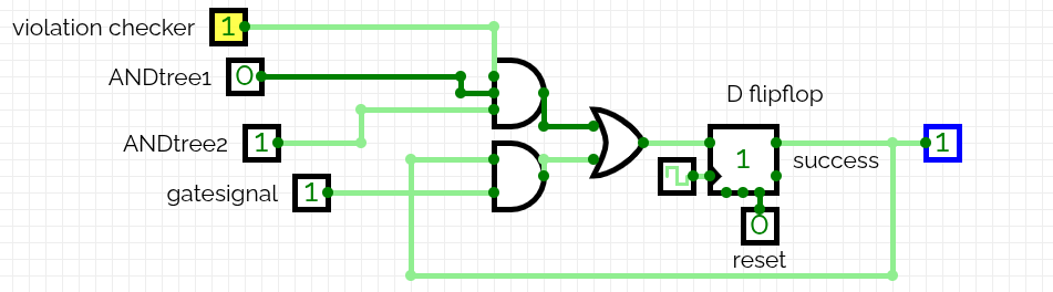
pin I actually care about: success itself. Traced its own gate directly and found a single
a32o_2 cell, reading its own current output back as one of its own inputs; it is more like a sticky latch,
once it is high it's high till cleared, but this gate isnt that exactly but close!
This is the circuit which drives the success output, and it feeds itself back as one of its own inputs
One inputs of that gate is fed by an AND-tree, and the AND-tree is fed by some other logic further back. I tried following
it backward, gate by gate.
this is hard; the dependency circuit is getting huge with each stage to track with,
and what any of these intermediate signals actually mean/
Tracing back to input port from the success is harder than expected. So I flipped the approach: instead of tracing from the
answer back to the start,
I'd start from the input pin and watch what happens as bits actually move through design.
The flops that are doing the same; everytime I ran
I started with sending sequences of 1's and 0's, and watching the internal flops,
there are total 92 flops in the design, and what changes there in each cycle.
I ran this almost 7-8 times then looking the bits then, a few of them caught my attention;
not because of what they are computing, but because they looked identical no
matter what sequence I fed in. Tried all-zeros, alternating, different patterns, even the winning sequence didn't change them;
same flops, same exact thing happeneing, every time.
something that doesn't care about the actual data, and changes every clock; that's a real, distinct thing.
Checked this happening in multiple runs, not just one run: out of all 92 flops in
the design, exactly 10 are identical and doesn't depend on the input.
4 of them repeat with a period of exactly 11, and I read them together, thought its some sequence generator
4 more of the remaining 6, changed every 11 cycles and bacame zero at the end, idk why, but they change together, must be another seuqnece generator;
now the last two, one of them goes high only at the 121st clock cycle (0-indexed), must be the last-bit flag,
so the required sequence length is 121, not 122;
the other one I don't know yet. Let's call the first
one counter type 1. I found I am incorrect here a bit later, not right now.
So, there exist a counter that resets every 11 cycles and another reset at 121 cycles, I am almost certain
for a giveb bit-index they are in same stateif either index%11 is equal or index/11 is equal.
Built this one out afterward as a real circuit, using the same gates I found in the gds file,
to watch it happen with my own eyes:
counter 1, built and verified as a real CircuitVerse circuit; cropped to exactly one
full 11-cycle loop, back to zero
Nice, so something must be happening every 11 cycles. And this is resetting every 11 cycles.
Didn't observe it as a mod-11 counter, but something to relate with the number 11, at least.
I thought it's not a plain counter - was wrong
Seeing it I thought it's not a clean 0,1,2,...,10 counter; the numbers (states) are different.
Looked at the actual gates behind it:
only 11 gates total for all four bits are interdependent, now I am sure they are doing something together.
A textbook mod-11 counter; a plain
binary incrementer, a comparator for the value 10, a mux to force the reset; needs closer to
19 (this is the number I got when I used my code).
the "obvious" way (~17 gates, an adder plus a comparator)
wire g1 = !ctrl & 1'bx;
wire g2 = !c & !a & b & d;
wire g3 = ~(c ^ g1);
wire g4 = !((c & g1) | d);
...
always @(posedge clk) begin
  a <= g_a; b <= g_b;
  c <= g_c; d <= g_d;
end
A normal 11-cycle counter, looks like the left side; an adder with a reset condition.
This doesn't. My first thought was that someone had hand-picked this
exact scrambled sequence to save a few gates. Thinking about it more, nobody sits down
and hand-derives an 11-state scramble to save 8 gates (maybe they do this at the JS, for them smaller and faster is better).
This is type of thing we do; writing a plain
case statement for it and let the synthesis tool implement however it wants to
optimize the implementation. This is intentional,
maybe; just might not be intentional by a person.
the tools found something smaller than what we write by the hand
There's a second one of these, running slower; changing once every 11 cycles instead of every
cycle:
distinct values visited, in order: 0, 4, 8, 12, 2, 6, 10, 14, 1, 5, 9, (back to 0)
two counters, two different timescales, both cycling through 11 states; they exist for some purpose
What are these actually for?
Before getting to that, I found that the thing I mentioned earlier was wrong. I thought about 2 things:
First, if this is a normal increment-and-compare mod-11 counter, the states should just go
0 to 10, in order. Maybe a tool optimized something about it,
but it is not supposed changed the counting behaviour itself.
Second, if this is a case statement given to the tool, with the tool free to
pick whichever 11 state values it likes; how it even land on this specific sequence?
Doing this manually felt like over-engineering for 8 gates.
Thought it is like some well-known thing like the grey-code optimized for sequence
Looked at the numbers in binary,and noticed;
one of them flips every 1 cycle. Another flips every 2 cycles. Another every 4. Another flipped at 9th cycle,
but then reset before 16th cycle.
that's not a scrambled sequence; that is what a normal binary counter's bits look like,
I just read them in the wrong order
Then I re-read the sequence I have in the correct order:
so it was never scrambled at all; that was entirely my own incorrect labelling
This also answers the first point there's no separate comparator type of thing near it;
like is_equal_to_10. Which felt like it should be like the second thought; a
case statement, left for the tool to turn into whatever gates it wanted, which creates an FSM.
Going forward from both counters to see where the output goes; some decoding logic; the bits arriving at the same state of
the fast counter get routed to the same logic, every time. Confirmed this by seeing a few of the flops post elimination. So
when the bits are sent, they go to the same place; when the counters are in same state, confirmed this by sending a lot of sequences.
Different sequences when sent, for each counter1 state there are 2 tihings happening: whenever there is a bit in the column (index%11) one of the flop toggles,
the other observation is whenever there is 2nd bit in the same counter's state the other flop goes high and never back to zero again till reset.
Here, the first flop's input is getting fed into the second flop's input, so they are working together.
They are keeping track if they've seen at least
two incoming bits at their own specific states; not raw counters, but sticky flops
Sent 0, 1, 2, and 3 . . . stars into the same column and watched both bits directly.
First one goes high on the first
high bit; the second goes high on next high bit, and next bit both stays high, so its counting whther the column have 0 or 1 or 2 or >2 bits.
so it's "at least 2," not "exactly 2"; there is not wat that gates can tell difference between more one's
implementation of >=2 counter, built and verified as a real CircuitVerse circuit, the unlabelled input is reset here
Flops and routing together means something
Bits landing on the same state of the fast counter goes into the same flops;
So, it's clear the same index % 11 is a column(when arranged as 11x11).
Then looked for the equivalent for the slow (type-2) counter; the "every
consecutive block of 11" grouping, which is a row (when arranged as 11x11), didn't find anything.
To check this properly, I paired
three different bits as high in the same row; gave three different and non-overlapping
flops a few times, different from how the column check is happening. Not checking rows the same way (>=2 checker), then?.
so columns exist, rows don't. what is the rest of the circuit checking?
Some flops take input by both counters. Given
each counter's value maps to a row or a column, a signal depending on both, may be
somegrouping; diagonals was my next guess, especially with two
independent counters there trying to define one.
let's define a {row,column} pair be a cell.
When checked against the cells these flops responds to, a diagonal needs
every cell of it to have same row − column (or row + column)
value. The cells spread across 6 different row−col values and
8 different row+col values.
not rows, not diagonals; whatever it is, it's some other check
The flops that are reacting are a for some scattered cells I went looking elsewhere for a clue,
which sent me toward the output generator next.
Also, followed two of these anyway, one from this checking unknown, one from a column.
Both are feeding into a shared AND gate, which fed into another AND stage, which fed straight into the exact logic
driving success at the end.
One more counter
The two counters I found don't care about input. So I was thinking if there is
another counter that cares about input bits,like maybe counting the stars?
seeing the cycle counters before, I wanted to check if there is any counter
for the total number of stars too.
Sent inputs with the total number of 1's ranging from 0 to 121, in multiple simulations,
and captured every flop every clock cycle. Looked for the pattern a real binary
counter's bits show: one flop toggling on every new star, another toggling every 2, another every
4, every 8, and so on.
Checked this properly by sending the same number of stars in different patterns and watching the same
flops. They all behaved the same way regardless of position, so this is a real, genuine bits counter.
this one is counting the number of bits, so if it's counting, something downstream probably cares about a specific count
Went looking for a flop that goes high only at one specific count and stays zero everywhere else.
Found a few candidates at first, but none of them held up once I re-tested with different placements of
the same count — each one turned out to already be a comparator or the overflow detector I'd found
earlier, just coincidentally triggered early by whatever arrangement I'd used the first time. No dedicated
single-count flop turned up anywhere.
worth noting though: 22 total stars, combined with all 22 of the column/region checkers already reading "at least 2," would pigeonhole into exactly 2 each — a real, sound argument on paper, even without proof the circuit actually uses it this way
Traced success's own complete dependency chain anyway, out of curiosity, and this counter
was genuinely in there — all five bits. Which was strange, given I'd just failed to find any flop
reading them for a specific count.
wait; if none of the FLOPS check for a specific count, maybe I was searching in the wrong place entirely
My search had only ever looked at flops — stored values. But nothing requires the actual check to
live in a flop; it could just as easily be a plain, unstored, combinational gate sitting between the
counter and whatever reads it. Went looking again, this time tracing forward from the counter bits
directly instead of scanning every flop in the design.
Found it three gates downstream. One gate ANDs together bits 1, 2, and 4. A separate little chain NORs
together bit 0, bit 3, and one more flop, which comes out to !bit0 & !bit3 once the
extra term (which turned out to just sit at 0 for every count I tested, not actually part of this) drops
out. Combine both halves together and you get bit4, bit2, bit1 all high, bit3 and bit0 both low —
which is exactly 22 in binary, and nothing else.
Checked the whole range from 0 to 33, and it fires at exactly one value. Confirmed with different
placements of 22 stars, several times over — same result every time.
this is a real, dedicated "is the total exactly 22" check; it just isn't sitting in a register the way I assumed it would be
Traced it one gate further; it feeds directly into success's own decision gate, confirmed
net-for-net, not just somewhere in the same neighbourhood. Checked whether the reverse also exists
somewhere — a flop or gate reading low only at exactly 22 — but this specific signal only ever
gets used once, in this one direction, feeding forward into success and nowhere else.
Only five bits though, so this thing can only count up to 31 before it wraps back around to 0 and
starts over. Went looking for a sixth bit specifically, sending well past 31 stars to see if something
new kicked in around there. Nothing did — checked the whole range up to 121, and no new flop ever
showed up. Five bits, no more.
but then what happens at 54 stars? that's 22 mod 32; the exact same five bits, same pattern, same "this is 22" signal firing, unless something else is stopping it
How "more than 2" gets caught
Seeing the input sequence we already have, I am sure if arranged as a 11x11 grid,
rows and columns have exactly 2 bits.
But whats there in by mind is if a the flop I first assumed the answer freeze and can't tell difference
between 2 and 3, how does the circuit know if there are additional 1's? Then checked the states:
flop1 and flop2 together go through four states; 0 seen, 1 seen, 2 seen, then >=3 seen. And each
have different states for the 2 flops that are counting number of bits there.
So both flops together can tell the difference between 0,1,2,>=3.
My best guess reasoned from the wiring: something later in the circuit
reads both flops per group, turns the success off if any hits state 11 i.e. >=3 1's.
Tested this directly: the actual solution with one extra star forced into an satisfied group
gave TRY AGAIN, every time. Found another flop, separate
that flips from 0 to 1 the moment this happens and stays there; which deeds into one of the
three conditions success's gate that needs all to true. When it flags a
violation, that condition breaks, and success never become high.
So, what does the winning input actually need to look like
Tracing back through all of this: every group of cells sharing the same index % 11
— a column — needs exactly 2 bits high. Same for every irregular region the two counters
together identify. That's 121 real positions worth caring about, out of the 122 the
waveform showed; dropping the last one suddenly made a lot more sense.
The second input to success's own gate only reaches 1 right at the very last real cycle
— traced to a flag that flips exactly once, at cycle 121, and nowhere else. Whatever the solver
handed back as a 122-bit answer, the circuit itself is telling me plainly: it's 121 bits that matter.
Having only looked closely at the fast counter and what comes right after it, the pattern was already
consistent enough to draw the obvious conclusion: every block of 11 consecutive input positions, and
every set of positions sharing the same index % 11, should end up with exactly 2 bits high.
Arrange the dropped 121 bits into an 11×11 grid, and those two conditions read exactly like rows and
columns.
Constructed an input satisfying that — 2 per row, 2 per column, nothing else assumed — and
ran it through.
TRY AGAIN
again. hehe.
Checking the ROM
Wanted to understand how the output generator itself actually produces these messages. Turned out to be
built around a small ROM — not a state machine quietly generating the bit sequence live, which is
what I'd assumed up to this point. Looked through its contents from there, and everything else follows the
same way it did before:
EMPTY SKY
BIG BANG
(* TWO STARS *)
TRY AGAIN
To check properly, I needed to understand how the output generator actually works. Found that it's
built around a small ROM.
up to this point I had assumed there was some kind of FSM generating the bit sequence live; turned out it's a lookup table
Inspecting its full contents gave me exactly one more string:
TWO"NOT TOUCH
so what now; two stars, never touch? if they did, would something explode? probably not, but it's one of my thoughts
Read it again: two [somethings], never touching.
so two bits never touch each other? touch, meaning what, exactly? adjacent? and should that be true for every input, or?
Reconsidering the 122nd "don't-care" bit from earlier observations; dropping it left exactly 121, which arranges
cleanly as an 11×11 grid. Checked the Z3 solver's winning sequence showed something: sure, no
two of the "high" bits sat next to each other, not even diagonally.
so now bits are stars?, and stars don't touch. tried constructing my own arrangement by hand with no two adjacent bits;
still just gave TRY AGAIN, so clearly not any non-touching arrangement works. something else is being checked too.
Searching for what this string can mean: found existing puzzles called Star Battle;
place stars on an N×N grid (divided into N regions) such that every row, every
column, and every region contains exactly two stars, and no two stars touch, even diagonally, so now it is clear that we need to look at 121 bits not 122.
The "2 stars per region" variant (as opposed to the more common "1 star"
version) is a completely standard, a commonly-played version of the same puzzle. Which also finally
explained the ROM string: TWO"NOT TOUCH is literally the game Star Battle's
alternate name; "Two Not Touch."
so that's what the unnamed group of 11 sticky latches actually was, back when I was staring at the circuit; not rows, not diagonals; regions, exactly like real Star Battle uses
One more thing I wanted to check: given I found this string by reading the ROM contents,
was there some input that can accidentally would have revealed that last string itself
thought i might have missed some pattern in initial exploration
, or was it just hiding there, permanently
unreachable? Ran it through the solver, asking for any input that can ever produce
those bytes; solver returned no solution at all, but when I send input that satisfies 3 of the rules, but not the touching rule, I saw the output TWO"NOT TOUCH.
So it IS reachable from input sequence but the solver was not able to converge
which is a great detail; hiding the puzzle's own name inside it
So: I found the solution and functionality, Right?.
solution to what, though? I didn't actually have the question yet
Which means the real remaining task is recovering the puzzle's actual
region layout from a chip that only ever outputs pass/fail on a full grid.
figured this part would be genuinely difficult; and, it was
Approach 1: reading the flops directly
While looking into the output generator earlier, I'd already been wondering what all these internal
flops were actually counting or storing.
there's obviously some kind of bookkeeping happening cycle by cycle in there which we already found; but what, exactly?
Tracing backward from success gave a list of flops that directly, combinationally feed
its decision. From there the natural thing to do was just start looking at them directly; feed all
zeros, all ones, a single 1 bit walked across every position, and watch which flops actually change.
this is basically the "just send inputs and watch what changes" idea I had from the very start, but couldn't find a reason before
One thing that fell out of that early exploration was a sawtooth, which you just read about before a min.
Connecting this to the circuit exploration, if a flop only cares about "has this row seen 2 stars"
or "has this column seen 2 stars"; that's not actually useful to me. Rows and columns?;
I already know exactly where they are, just from the grid's own shape. What I don't have for free
are the regions; the one part of the puzzle, and now I'm interested in this.
Regions have exactly one rule worth exploiting: exactly 2 stars per region. So, the obvious first idea:
place 2 stars somewhere on the grid, see which flop goes high. Do that for every possible pair of
cells; C(121, 2) = 7,260 combinations.
that's a lot of pairs, but maybe still doable?
But wait: I don't need every pair to check with. If I fix one cell and pair it with
every other cell in turn, whichever flop goes high consistently for that one reference cell already
tells me its whole region in one pass.
So: started with cell 0, paired it with all 120 other cells, and recorded which flops changed for
each pairing. The working assumption: seeing 1 in any flop means "these two cells are in the same region"; though
that's clearly not exactly known yet, since a flop could possibly go high for many unrelated
reasons. There should be some flop, among the noise, that should also be going high for the actual reason I
am looking for.
flops with any nonzero high-count: 24
  reg 2293: high for 110 of 120 partners
  reg 8219: high for 107 of 120 partners
  reg 2542: high for  28 of 120 partners
  reg 2708: high for  21 of 120 partners
  reg 8086: high for  13 of 120 partners
  reg 1228, 1230, 1250, 1258, 1259,
  reg 1260, 1261, 1264, 1809, 2037, 8602: all tied at exactly 11
  reg 8092: high for   9 of 120 partners
  ... (and a handful more, with single digits)
Intuitively, numbers like 110 and 107 obviously made no sense; but "obviously" it isn't a real reason
to throw them. The smaller end had an actual, defensible reason to eliminate: the minimum possible
region size is 3, since 2 cells that are adjacent can never hold 2 non-touching stars in the
first place. That removed a few outright.
Still a lot of them left. Then new thought: if one region ate up 100+ cells, the other ten regions; which
each need at least 3 cells of their own; will not have room left to exist. That's a real,
ceiling, not just my feeling, and it eliminates the 110-partner and 107-partner flops.
Next, a simpler geometric thought: if a set of cells genuinely belongs to one region, every cell in it
should share an edge with at least one other member of the same region; the whole thing has to be a single connected
component (every cell is reachable from every other). Applying that; was able to strike out most of what was left.
This got it down to just two real contenders; both looked like legitimate, connected, sensibly-sized
shapes:
candidate A — flop 8086, size 14candidate B — flop 1250, size 12
Both connected, both have sensible size, both passed every geometric check I had at that point. New idea:
if these cells genuinely belong to one region, then every pair within it should light up the same
way; not just pairs involving my original reference cell (cell-0 in this case). But checking every possible pair inside
both candidates is not necessary to remove one.
the competitive-programming instinct kicked in here; don't brute force it, find the shortcut
The shortcut: just take a cell that sits in the overlap of both candidates, and re-test it
against every cell in both candidate lists. Whichever flop stays perfectly consistent; firing for
every true member, silent for everything outside; is the real one.
yellow = claimed by both · green = only candidate A · red = only candidate B
using overlap cell 12 as the new reference:

  against candidate A's cells:  reg 8086 high 13/13 — every single time
  against candidate B's tail:   reg 8086 high  0/6  — never once

  against candidate B's own cells: reg 1250 high only 1/11 times
  (it doesn't even agree with itself anymore)
Now, it's obvious; candidate A(region A) still fits perfectly from a different angle, candidate B
should be eliminated. And the winning bit sequence I already had from the solver has also satisfied exactly this
region's rule, cleanly, no coincidences.
So: found a region. Marked it. Then picked a fresh, still-unmarked cell and repeated the whole process;
this time adding one more elimination rule: if a candidate's cells overlap with a region I had already
confirmed, throw it out, since no cell can belong to two regions at once. Repeat that enough
times and the whole puzzle will be what we get; and the very last region doesn't even need whole extraction: whatever
cells are left over once ten regions are found have to be the eleventh, by elimination.
the whole procedure, summarized
mark all cells as unclassified
confirmed_regions = []

while unclassified cells remain:
    ref = any unclassified cell
    for each other cell j:
        place 2 stars at (ref, j), run the chip, record which flops went high

    candidates = every flop whose "fired-with" set, plus ref itself:
        - has at least 3 cells                      (2 adjacent cells can't hold 2 stars)
        - has at most ~100 cells                     (other regions need room too)
        - forms a single 4-directionally connected blob   (regions aren't scattered)
        - can actually fit 2 non-touching cells inside it
        - doesn't overlap any already-confirmed region

    if exactly one candidate survives:
        confirm it as the next region
    elif multiple survive:
        pick a cell in their overlap, re-test it against every cell in each
        candidate, keep whichever flop stays perfectly self-consistent
    mark all of that region's cells as classified

# whatever's left after 10 regions are found is automatically the 11th
Approach 2: symbolic dependency tracing
The eventual approach: symbolically trace, for each of the relevant internal counter flops,
exactly which of the 121 grid positions it provably depends on; not by guessing-and-checking
specific inputs, but by building an actual symbolic formula for each flop and reading its
dependencies straight from that formula. That came back with 11 irregular groups of cells; the
regions; which, combined with the winning bit sequence, reconstructs the entire puzzle: question
and answer, verified by hand against every rule.
the recovered puzzle, solved; two stars per row, column, and region, none touching
Now look at the puzzle. Found something?
need a hint?
Don't just look at the sizes of the regions; look at their
outlines. Three of them; read from left to right across the grid, they mean something.
okay, just show me
It's the letters JSC; short for
Jane Street Capital, hidden in the shapes of three of the regions.
Solve it yourself
Since I ended up with the actual puzzle question and not just its answer, it felt it right to let you
solve the exact same grid the chip is checking, by hand, rather than just look at the picture above.
Click a cell to place a star, click again to mark it excluded, click once more to clear it. Regions are
colored the same way as the grid above.
click cells to place stars · every row, column, and colored region needs exactly two
0 / 22 stars placed.
Ohh, you're still here?
then answer a couple of questions
1. What is my favourite language?
2. How many times did TRY AGAIN show up before it stopped feeling personal?
Closing thoughts
So, what does "reverse engineer this ASIC" actually mean, in the end? Make success go
high? Extract the string? I ended up with both, plus the actual logical function the circuit computes,
plus the puzzle it's secretly checking, plus few Easter eggs. Maybe that's what was
strictly asked for.
is this the end? did I leave something on the table? I genuinely have no idea of anything else left to chase down at this point
Whatever it is, I'm satisfied with where this landed; which matters more to me than it probably
should, given the AOF one still stings a little. Not the "I got everything" kind of satisfaction; but
the "I actually finished this one" kind. That's really the whole point of writing this up.
One random line
When a puzzle tells you it contains Easter eggs, it's probably worth looking at the weird stuff you
initially decided to ignore.
03 / easter eggs
The weird stuff.
Stuck on what the 121 bits meant, I went looking for what they told us was hidden.
After getting stuck on what the winning input meant, I remembered the puzzle's note:
"We hid a few fun Easter eggs in the circuit and in the repository (including in parts you
don't need to look at to solve the main puzzle)."
Maybe hunting for those will give me some clue to work with.
A leap second
First thing I actually remembered finding; though I lost track of which file it was in; it was a
date with year 2016 somewhere. Went through everything looking for it again, and found it in the VCD:
Sat Dec 31 23:59:60 2016. I didn't even notice the ":60 seconds" part at first; just that
the year seemed like an odd thing to include. Checked for what have happened that day, and: a leap second got
added to the time right at that exact moment. A real, valid, unusual timestamp. One Egg found,
YAY!.
the leap second mentioned in the VCD file
The row of cells that don't connect to anything
Earlier, while reconstructing the netlist, I remembered seeing two odd custom cell types:
INTERNAL_3 and INTERNAL_7; sitting at odd; negative Y coordinate,
completely disconnected from the rest of the circuit. Didn't matter for making success go
high, so I ignored it at the time. But why at that specific position? And why 21 of one type and
15 of the other? Felt like it had to mean something, I didn't see them yet.
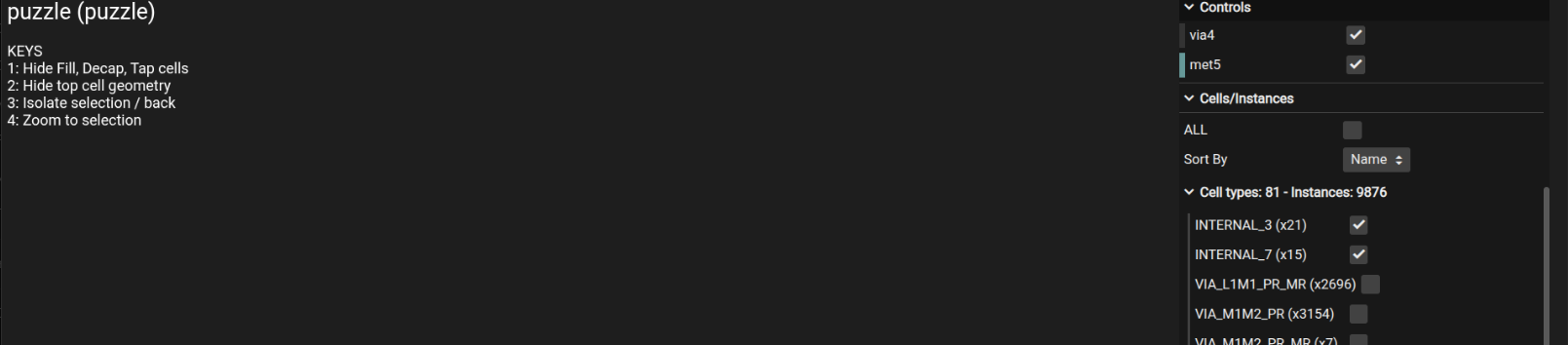
I tried looking at the GDS in the browser-based
tinytapeout viewer first, deselecting every other layer
to isolate just those two cell types. Got... nothing. A blank screen.
is this a prank? intentional, or just a bug in the viewer? whatever it is, not helpful
the viewer that showed me absolutely nothing
Next attempt: extract just those specific cells into their own tiny standalone GDS file so there'd be
less to go wrong. Got back a file; I expected all 36 placed copies, but only found 1 rendered.
Opened it anyway.
just... a rectangle? okay, so what am I supposed to do with this?
one rectangle. looks cool.
Gave up on the browser viewer and opened the whole thing in KLayout instead; I
looked at the full circuit in KLayout before, just to look, without doing anything with it.
circuit looks beautiful, by the way. kidding; it's just a circuit
Went hunting for that negative-Y row specifically this time. Toggled layer visibility one at a time,
didn't see it at first,
must be a bug then; but a negative Y position? that's outside the die entirely, isn't it
then scrolled down past the main circuit boundary and there it was.
A row of small rectangles, colored a clean green, clearly not part of any real logic. Some short, some
long.
are these... zeroes and ones? no, that doesn't make sense. long and short; wait. oh. this is Morse code.
Went back to the properly-extracted 36-cell version with this in mind; this time the dots and
dashes were very clear. Wrote the pattern out on paper by hand:
pattern
letter
dash dot dot dash
P
dot
E
dot dash dot
R
… which spelled out:
PER ARENAM AD ASTRA
the morse code that is in the gds file given, filtered with contrast to improve visibility
Latin. Ran it through a translator: "through the sand, to the stars"; google search revealed that it's a play on the actual Latin
motto per aspera ad astra, swapped "hardships" with "sand." Genuinely nice tweak for a chip made of
silicon.
maybe it's the hardware background talking, but I really did like this quote
And the custom cell names suddenly made sense too: INTERNAL_3 and INTERNAL_7;
the dot:dash width ratio is exactly 3, and the gap timing ratio is 1:3:7. The names are the
Morse timing specifications.
side quest: is there a real historical Morse message sent around that exact leap second; like, to aliens, or something equally dramatic?;
Went looking. Search results (both a Google Search and AI research) revealed nothing real.
must be overthinking it, almost certainly.
which I do, on a lot of things
A string that is inside the raw data
Thinking about that VCD file's hint; "leave no stone unturned"; I thought if metadata
anywhere else might reveal something. Checked file modification timestamps: nothing. Checked git commit
history: one single commit, just the initial upload. Ran a basic steganography extractions on the PNG
image: nothing.
Then I tried something: since the files stores the data in bytes, I scanned the raw file
bytes directly for all files, looking for any run of at least 3 consecutive bytes that read as alphabets. Found many,
one of them that got my attention to:
EGG', sitting right there in the raw file bytes of the layout image.
wait; does this mean there's something to decode around this area?
Looked at lot of of bytes on either side; nothing else is readable for around 200 characters either
way. Given I am already hunting for Easter eggs, finding the literal word "EGG'" in the file
felt too perfect to be coincidence. But there was nothing more I can reason about it; tried extracting that segment,
and the moment I actually
decompressed that section of the file, the string disappeared; it only existed in the
compressed bytes, never in the real image data.
maybe it really is coincidental; or maybe they were trying to tell me something and I just couldn't reason. I don't know. I left it there.